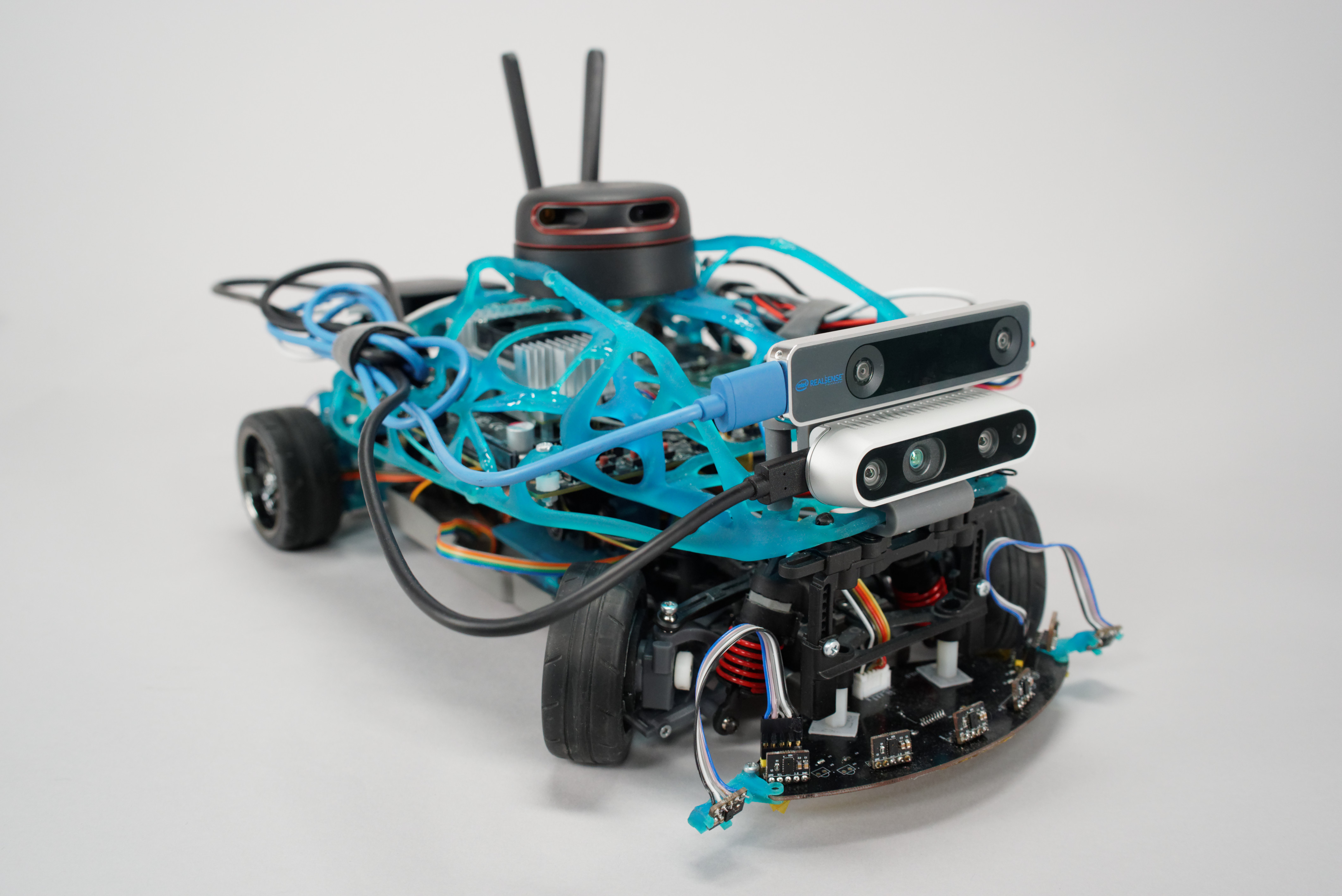
A small-sized model of an unmanned vehicle
A small-sized training and demonstration software and hardware complex for developing skills in creating unmanned autonomous vehicles: small dimensions and modularity of the design provide for remaking the model for various missions
Task
The creation of control systems for unmanned vehicles is one of the main activities of the Autonet roadmap of the National Technological Initiative implementing the state policy in the field of developing the national scientific and technical potential. One of the goals of the program is to increase the quota of domestic manufacturers of intelligent transport control systems for unmanned vehicles in the Russian Avtonet market in the amount of 60% by 2035. Russian automobile concerns (KamAZ, GAZ, AvtoVAZ, UAZ) have already started active development in the field of autonomous traffic systems several years ago.
For working on such scale and intensity, specialists of high qualification are required and training enough of those within a short time is essential for the implementation of state policy.
To educate students of technical universities and improve the skills of already working employees, at the TestBed demonstration training ground for new production technologies at the NTI SPbPU Center, a demonstration training platform was agreed to be developed, i.e., an unmanned vehicle model that meets the following requirements:
- Inclusion of all the main types of hardware and software components used in the design of real autonomous transport systems
- Use of advanced technologies of technical vision, machine learning, simulation, etc.
- Modularity providing for configuring systems for various missions
- Use of open-source software to provided for the freedom of further modification of the device
- Expediency in operation, i.e., the possibility of transportation and use in a limited space.
The project is carried out jointly with the SPbPU Center for Computer Engineering (CompMechLab) as part of the educational sphere of the NTI SPbPU Center program, namely the development of the TestBed training ground of the NTI SPbPU Center and educational activities on the basis of TestBed for instruction and advanced training of scientific and engineering personnel, and the presentation of advanced developments and competencies in the field of new production technologies for government officials and representatives of industrial enterprises, small and medium-sized businesses.
The developed model will be part of the material and technical unit of the training ground, the opening of which is scheduled for 2020.
Solution
The hardware and software platform is based on the NVidia Jetson TX2 microcomputer and the deeply modified Traxxass 4-Tec 2.0 chassis.
The composition of the model includes:
- Standard sensors: encoders, 10 high-precision distance sensors, a lidar, depth camera, tracking camera, 4 industrial video cameras
- Control boards for the hardware component of the chassis (development of the ISSDP laboratory)
- Software for the control on the device is based on the ROS Melodic framework:
- Mapping block (cartographer)
- Navigation block
- Odometry block
- Motion control block
- Communication block
- Block of integration with hardware under the control of an STM controller.
The software was developed at the ISSDP laboratory with the use of open-source software.
The software modules that collect and analyze information from sensors use:
- Technical vision technology (collection and integration of information from cameras)
- machine-learning technologies (pedestrian recognition algorithms)
- artificial intelligence technologies (calculation of the route to avoid dynamic objects / overcoming barriers in an intelligent control system).
A virtual model was also developed to simulate functioning, which allows debugging software without a physical model, which considerably speeds up the development process.
The SPbPU Center for Computer Engineering (CompMechLab) is finalizing the chassis to reduce the turning radius; currently, it is developing a new supporting structure for the equipment with the use of modern computer-generated simulation and engineering technologies based on the principles of bionic design.
Due to the listed set of components, the model will be able to:
- Draw maps and read them
- Search for the shortest route to a point on the map
- Skirt dynamic barriers
- Recognize the various signs and attributes of the road environment (markings, traffic signs, pedestrians, other vehicles) and take actions in connection with those
- Make overview images (surround view, bird view, orbital view, etc.)
Advantages of the solution
- Uniqueness: studies conducted by the implementers at the ISSDP laboratory prior to the work start showed non-existence of analogues of the training and demonstration complex of this level
- Efficiency: the entire arsenal of technologies currently used by designers to build Advanced Driver Assistance Systems (ADAS) is assembled in one device
- Relevance: the presented hardware and software solutions correspond to the state-of-the-art developments in the industry
- Accessibility: the platform is easy to transport and can be used in a regular classroom due to its small dimensions (40x25cm) and a small turning radius (under 40 cm)
- The platform provides an opportunity for a more generic study of technologies for collecting, processing and transmitting information from various sensors for the creation of information systems of a different kind.
Details
Project stages:
- Development of a test sample with limited functionality (January 2020)
- Development of a prototype with the ability of drawing maps of the area, navigation, orientation and barrier avoidance (2020)
- Development of a commercial sample; implementation of ADAS (2020 - 2021).
The development of a test sample (stage 1) is completed. Currently, work is underway to modify the test model and expand its capabilities as part of the tasks of the stage 2.
Tasks solved at the 1st stage of development:
- Development of hardware solutions to ensure the control of SMAC components (engine, servo-steering wheels, speed sensors, proximity sensors, cameras, etc.);
- Ensuring the interaction of the SMAC components
- Refinement of pedestrian detection tasks based on information from all-round cameras
- Automatic stop upon detection of barriers and / or pedestrians that jeopardize the further movement of SMAC
- Interaction with the web-interface of the demonstration training ground and real-time transmission of the requested information: speed, wheel angle, distance to each of the proximity sensors, as well as video imaging from 4 all-round cameras with pedestrians detected on them
- Movement with the use of the remote control.
Currently (April 2020), stage 2 of the development is underway.
Since the provision of autonomous car movement is a set of solutions to many different problems, at the stage 2 of work, it was agreed to expand and deepen the model’s capabilities in the spheres of spatial orientation, mapping, navigation in space, and interaction with tracking cameras and depth cameras.
- Development of software and hardware components for mapping, navigation, orientation and barrier avoiding
One of the most important parts of the hardware and software development was the description of the robot model in the Unified Robot Description Format (URDF). A URDF file is necessary to simulate the behavior of a machine in a virtual environment; it is also used to visualize the results of algorithms.
Gazebo was chosen as a physical simulator. To simulate the lidar, cameras and distance sensors, virtual models duplicating their physical properties were created.
For testing SLAM algorithms (simultaneous localization and mapping) and navigation, several virtual spaces were created with barriers of various configurations.
For the development process, the description of the virtual model included:
- 4 wheels
- Chassis
- Plate
- Tracking camera (Intel realsense t265)
- Depth Camera (Intel realsense d435i)
- Lidar (Rplidar A2)
- Inertial Measurement Units (IMU) (Intel realsense t265)
- 10 distance sensors.
The sizes and various physical properties of components, such as mass, inertia, etc., were described for the correct physical simulation of the model in a virtual environment. The description also holds data on the real locations and transformations (rotation) of the components by which the model transformation tree is built.
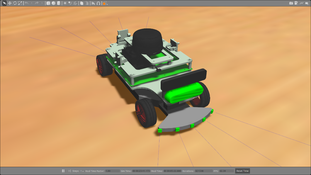
Virtual model in the Gazebo simulator
The simulator was used to conduct preliminary tests. The model, moving and guided in the proposed space, was to send out for displaying in the visual interface the information about its speed, wheel rotation angles, distances to range sensors, the current map of the area, the current movement path and movement target.
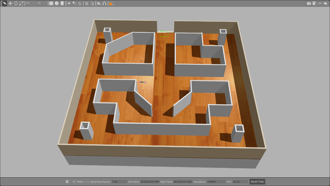
The initial map of the area in the Gazebo simulator simulating a physical environment with barriers for model passing through
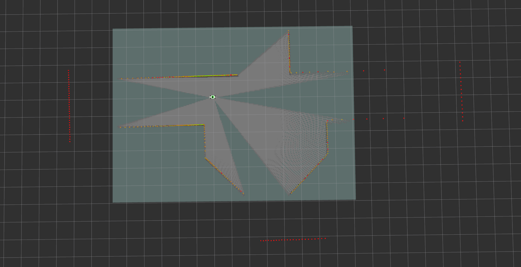
The area map created by the model using lidar data after switching on, prior to the start of movement
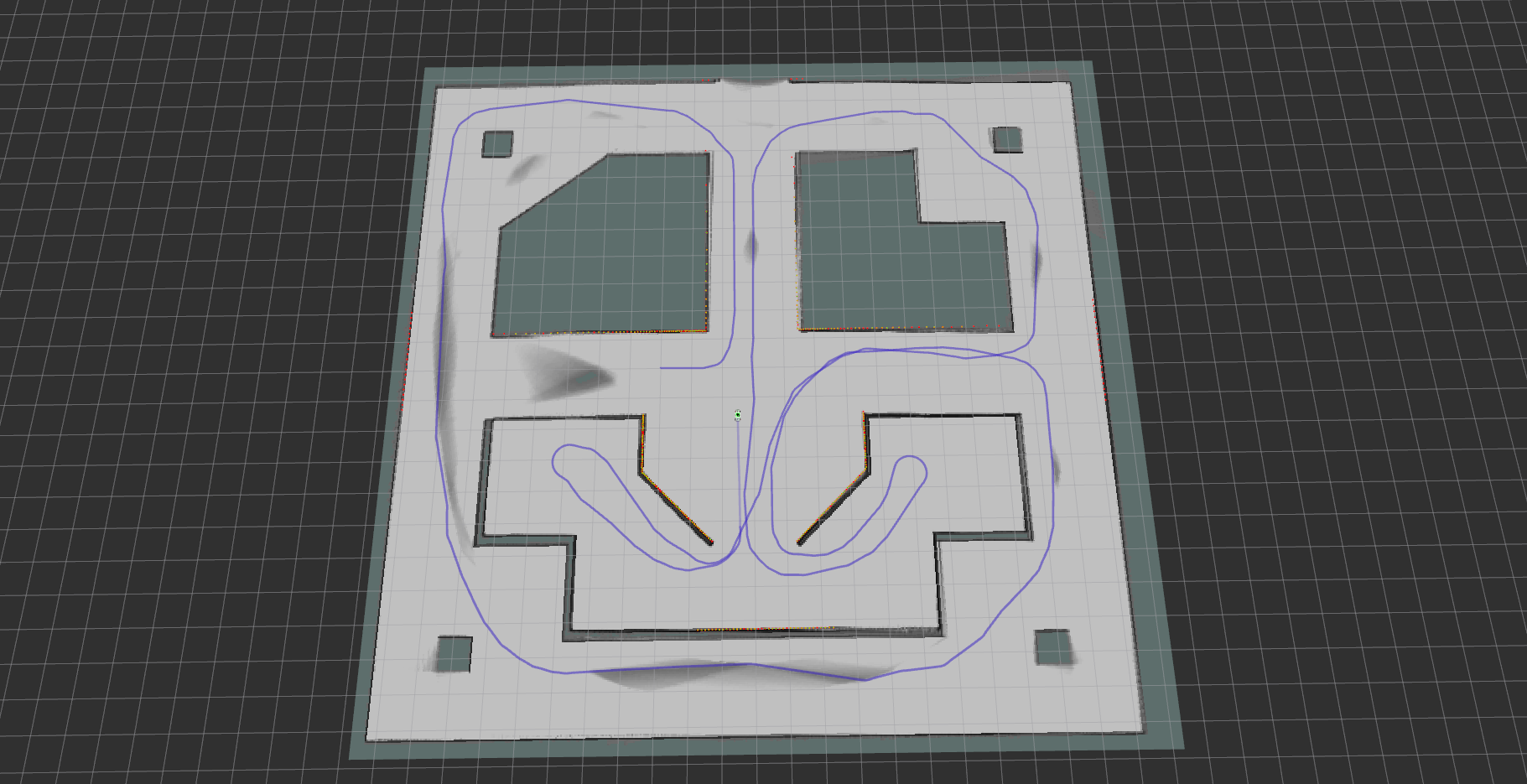
An area map constructed by a model using lidar data and a mapping block (cartographer) after the traversal
Testing of the virtual model of the platform showed that the software of the relevant blocks completely executes the tasks and works according to the plan.
The framework of stage 2 of work also includes the development and integration of a web interface for the control ling / displaying information and the final system setup.
- Finalizing the design of the physical model
To improve the technical characteristics of the platform, it was agreed to finalize the design of the model chassis in cooperation with the specialists of the SPbPU Computer Engineering Center (CompMechLab).
Employees of the Engineering Center made calculations of the current chassis design, in which the turning circle is less than 80 cm. To accomplish this, the steering gear of the front axle (steering knuckles, rods, levers) was reworked, due to which the angle of rotation of the front wheels increased from 30 to 45 degrees, and rear suspension changed, so that the rear axle also became controllable with an angle of rotation of 20 degrees and a separate servo.
Therefore, not only was reduced the turning radius of the model but also increased the flexibility in controlling the platform, since at high speeds one only can use the rotation of the front axle, thereby increasing stability, and connect the rear axle to the control at low speeds to improve maneuverability.
The upper deck (transparent plexiglass structure) will later be replaced by a deck engineered with the use of bionic design approaches. At the moment, employees of the Engineering Center have completed measurements and begun to develop the deck.
Technical advantages (at the current stage):
- Using ROS, an open framework for creating individual modules for SMAC
- Flexibility of the sensor sets used
- Mapping of the area, navigation, over passing barriers in real time
- Small dimensions; small turning radius.
Technologies
| Programming languages and frameworks | C++, Python, Kotlin, ROS, Cartographer, C, CubeMx |
| OS | Linux, Android |
| CVS | Git (Gitlab) |
| IDE | CLion, stm32cubeide, vscode |
Intellectual Property
Project team
- Project Lead: M.V. Bolsunovskaya, Director of the Industrial Systems for Streaming Data Processing Laboratory, Center of NTI SPbPU
- Hardware Development Team Leader: G.S. Vasilyanov
- Software Development Team Leader: S. Tammsaar
- Project Manager: G.S. Vasilyanov
Co-executor
- SPbPU Center for Computer Engineering (CompMechLab)
Customer
- NTI SPbPU Center
- Director for the introduction of new production technologies at the Center of NTI SPbPU at the TestBed training ground: D.A. Garanin, project leader at TestBed, Director of the Strategic Development of the Engineering Markets Research Laboratory, Center of NTI SPbPU